(→Circuitry Legend: Adding full legend page (still building, please preview and comment). ~~~4o66) |
m (→Major Changes: moved collapsible table example to correct position. 4o66 07:30, 18 Jan 2011 PST) |
||
| Line 207: | Line 207: | ||
:I would '''love''' to make little defaultly-minimized boxes to hide all of the additional circuit designs, so that it is not in the way everywhere cluttering the page, but I don't believe [http://www.mediawiki.org/wiki/Manual:Collapsible_tables this functionality] is enabled on this wiki :( |
:I would '''love''' to make little defaultly-minimized boxes to hide all of the additional circuit designs, so that it is not in the way everywhere cluttering the page, but I don't believe [http://www.mediawiki.org/wiki/Manual:Collapsible_tables this functionality] is enabled on this wiki :( |
||
| − | :Collapsible |
+ | ::Collapsible tables in enabled on the wiki, you simply have to code the boxes properly. |
| ⚫ | |||
| − | |||
| − | :{| class="collapsible collapsed wikitable" |
||
|- |
|- |
||
! This is the header cell, which is always shown |
! This is the header cell, which is always shown |
||
| Line 215: | Line 214: | ||
| This cell is not shown by default. |
| This cell is not shown by default. |
||
|} |
|} |
||
| ⚫ | |||
*Rewriting. |
*Rewriting. |
||
| Line 227: | Line 227: | ||
:Could you perhaps upload new pictures at a better angle? These are a little more clear but it is harder to see all the parts going into it, however if you were to be about the same distance away but made yourself a few blocks off the ground so we could see how everything went in that would be great. --[[User:Bosnity]] |
:Could you perhaps upload new pictures at a better angle? These are a little more clear but it is harder to see all the parts going into it, however if you were to be about the same distance away but made yourself a few blocks off the ground so we could see how everything went in that would be great. --[[User:Bosnity]] |
||
::Yeah, these are the third revision of those pictures, I just couldn't get things perfect. xD An overhead view would be better, but I'm not up to screenshotting it just yet. I believe they do a fairly good job though for their purpose. --[[User:Prettycoolguy|<span style="color: #333; text-shadow: 0px 0px 2px #000;">prettycoolguy</span>]] ([[User_Talk:prettycoolguy|talk]]) 03:47, 26 November 2010 (UTC) |
::Yeah, these are the third revision of those pictures, I just couldn't get things perfect. xD An overhead view would be better, but I'm not up to screenshotting it just yet. I believe they do a fairly good job though for their purpose. --[[User:Prettycoolguy|<span style="color: #333; text-shadow: 0px 0px 2px #000;">prettycoolguy</span>]] ([[User_Talk:prettycoolguy|talk]]) 03:47, 26 November 2010 (UTC) |
||
| − | :::Collapsible tables in enabled on the wiki, you simply have to code the boxes properly. |
||
| ⚫ | |||
| − | |- |
||
| − | ! This is the header cell, which is always shown |
||
| − | |- |
||
| − | | This cell is not shown by default. |
||
| − | |} |
||
| ⚫ | |||
==Offloading Basic Information to More Appropriate Pages== |
==Offloading Basic Information to More Appropriate Pages== |
||
Revision as of 15:34, 18 January 2011
| Archive |
|---|
| /archive |
Elaboration on several topics
Could the creators of these sections please edit to include more information on the workings of their devices:
- JK Flip-Flop
- T Flip-Flop
- 5/1 Clock
- 4 Clock
For the 5/1 Clock, it's just worded very strangely, and since there's no schematic, I can't build it to see what's going on. For the 4 Clock, elaboration on the workings of this clock, as well as a version of the schematic from the forums that fits the schematic style here would also be appreciated.
- Also, are there any more legitimate notes we need to add to the Important Notes section? Otherwise, I think the "needs expansion" note can go.
- --Allus 10:52, 28 July 2010 (UTC)
- I added some description to the JK and T Flip-Flops. I'll try build the wierd 5/1 clock.. Should I add the inverse Q to the Flip-Flops? (Is there even an easy way to do that without it getting bigger?) --Samonite 15:08, 28 July 2010 (UTC)
- I just tried the 5/1 Clock. If you connect the output to anything other than a door it wont work. This means that you can't connect it to any gates or just even Redstone torches. I have removed 5/1's from the article. --Samonite 15:45, 28 July 2010 (UTC)
- The 5/1 takes some tweaking to work, I just added it back not knowing where to check to discuss first I will test it again, until then ill remove it. --wolf_alex
- Looks like its not working how I want right now, but it works the same way when not attatched to doors, as I said it needs tweeking to work --wolf_alex
- I got it working, you have to build the 5 clock going counterclockwise or it wont work it seems, you also have to connect it at the same torch Edit: scratch that I messed it up again by testing if I could connect it with a different torch. Edit2: fixed it when I post it ill show how exactly to run it.
- Looks like its not working how I want right now, but it works the same way when not attatched to doors, as I said it needs tweeking to work --wolf_alex
- The 5/1 takes some tweaking to work, I just added it back not knowing where to check to discuss first I will test it again, until then ill remove it. --wolf_alex
- I just tried the 5/1 Clock. If you connect the output to anything other than a door it wont work. This means that you can't connect it to any gates or just even Redstone torches. I have removed 5/1's from the article. --Samonite 15:45, 28 July 2010 (UTC)
- I added some description to the JK and T Flip-Flops. I'll try build the wierd 5/1 clock.. Should I add the inverse Q to the Flip-Flops? (Is there even an easy way to do that without it getting bigger?) --Samonite 15:08, 28 July 2010 (UTC)
XOR Concern
I made an exclusive OR (XOR) gate (though I could've used an AND here, I just like exclusive OR) and where the levers go instead I put down redstone to lead it to lever. well the redstone went from the back (lever in diagram) then two tiles to the right then down to my lever, but the torch would stay lit no matter what I did, only until I removed the two redstone connected to the block (one off the back and the one diagonal) did it work again so it seems like having an active redstone line diagonal of a block (at least one with a torch on top and a torch on one face) disables the lever completely as the other lever will still trip the switch. Not sure if this is supposed to happen or if it's known it happens, but it's not on the page. I'm also not sure if it was fixed later and somehow retained in my client. --Enzer 08:23, 20 July 2010 (UTC)
Interesting page I have created
I have just created the page "Contraptions" where everybody could place their own creation(s) with the redstone, it can be found here. Hope you all apreciate.
- It seems to have been turned into a Redirect link back to Redstone circuits. I'd love to see a contraptions page, though, showing off what has been done, not simply an explanation of the tools available. You cant call a kid a carpenter if he just looks at his tools and says "wat". I might edit it later and give examples such as locks, wire-specific traps, and other machines, but I have recently been busy with other stuff (Touhou Project, Cave story :-) though. --Arlnet 18:48, 13 July 2010 (UTC)
- I support this whole heartedly, except it should include other contraptions, like auto cobblestone makers and mob collector/killers. EDIT: I've written up a page, and ironically could not find anything wired, so I've put the other ones I know in. Megadog 23:21, 14 September 2010 (CDT)
- I'd love a place to share non-basic redstone circuitry with others. the basics are great but its daunting to make advanced machines. my first major project i designed was a binary counter with a clock input that can be chained together to count as high as you want to, but i only got to 3 bits due to lack of redstone (so it could count to 2^3-1 = 7). --Cert 14:02, 16 October 2010 (CDT)
- The best place for a Contraptions page would be in the Tutorials section. DannyF1966 00:21, 17 October 2010 (UTC)
- Seems like the most ideal page would be Advanced Electronic Mechanisms.
- The best place for a Contraptions page would be in the Tutorials section. DannyF1966 00:21, 17 October 2010 (UTC)
- I'd love a place to share non-basic redstone circuitry with others. the basics are great but its daunting to make advanced machines. my first major project i designed was a binary counter with a clock input that can be chained together to count as high as you want to, but i only got to 3 bits due to lack of redstone (so it could count to 2^3-1 = 7). --Cert 14:02, 16 October 2010 (CDT)
- I support this whole heartedly, except it should include other contraptions, like auto cobblestone makers and mob collector/killers. EDIT: I've written up a page, and ironically could not find anything wired, so I've put the other ones I know in. Megadog 23:21, 14 September 2010 (CDT)
Jk Flip Flop
You do realise a Jk has Q and Q! as well as a clock, then J and K. The posted is missing the clock at the very least. --Zaneo 12:15, 27 July 2010 (UTC)
- I know that JK's have an inverse Q but to get it you could just add an inverter to the Q. The "real" inversed Q in the RS Latch was too hard to get. Should I extend the circuit to include the inverse Q? I don't understand the part about the clock. Can you explain that one? (Unclocked JK's exist if it was that you where referring to)--Samonite 22:45, 27 July 2010 (UTC)
- I know unclocked JKs exist, i thought that clocked was more common, maybe make a note that this is an unclocked one? --Zaneo 02:16, 28 July 2010 (UTC)
- Maybe. They are actually quite easy to make clocked. Just add an AND gate to the input. Then attach a clock to one of the inputs of the AND gate. You can do the same thing with the JK. Just use two ANDs.--Samonite 15:56, 28 July 2010 (UTC)
Diagrams
Regarding: "This page contains MCRedstoneSim diagrams for compactness and clarity of design." - I do not find those clear at all. After staring at the key for quite a while and even playing with the MCRedstoneSim simulator I still don't understand all of the icons. Could someone include screenshot of what each icon is supposed to represent, or can we switch to something easier to read? This, on the other hand, took a second but was otherwise easy and useful: http://minecraftwiki.net/wiki/File:StandardLogicGates.png
- They are kind of confusing, but I think if i was actually in game and looking more at the guide I could figure it out. Maybe we could reupload screenshots of the gates.Toadbert
- I second this. --Andrew12 23:25, 30 September 2010 (UTC)
- Yes, I agree. The new diagrams are extremely difficult to read. The in-game screenshots were far more helpful. --Declare variables, not war. 03:16, 28 October 2010 (UTC)
the diagram key would be easier to understand if it used better colors to signify if something is above a block, below, etc. the very slight grey coloring is hard to distinguish between white/yellow--Cert 18:53, 16 October 2010 (UTC)
Long term clock?
Could anybody explain to me, how could be latch used together with a pulsar to create a long term clock? I want to create something with a 15 second delay...
- Add as many t-flip flops to the end to make it as slow as you would like
- On a related note, can anyone make the C version of the T-flip flip work?
- i would not advise using a pulsar as clock. it switches too fast for torches to recognize.
- i just built the 'c' t flip flop design in an effort to save space, and when the input is on it just acts like a clock and burns out randomly. --Cert 18:47, 16 October 2010 (UTC)
Taken to its Logical Conclusion
A 16-bit computer designed for Minecraft by theinternetftw. RPS article link with Youtube video. --JellyfishGreen 12:55, 29 September 2010 (UTC)
Gif files on main page
Hi, this is the first time I've contributed to a wiki, apologies if I'm doing anything wrong. I wanted to point out that the gif files for the redstone circuits aren't animating on the main page, and it's not obvious just from looking at the gif that some of the circuits are two or three blocks high. I was looking at the XOR circuits in particular. If someone tries to build one of the circuits in mcredstonesim just by looking at the gif on the main page, it may take them a while to figure out where they're going wrong. DannyF1966
- This happened to me.
- Andrew12 23:24, 30 September 2010 (UTC)
- Ok, I updated the page to show that some of the gifs are animated. DannyF1966
- Gifs on main page are ok now, so removed my notifications. DannyF1966 19:26, 16 October 2010 (CDT)
- Ok, I updated the page to show that some of the gifs are animated. DannyF1966
Max distance runs
I've done some experiments and found that the farthest you can get from a redstone circuit is 17.5 chunks (281 blocks). In other words, if a clock generator is placed in chunk #1, as soon as you cross the midway point of the 17th chunk it will cease operating. Important to note that it will not begin operating again until you are within 10 chunks (160 blocks). I have only tested this in one direction (North/South) so I'm not sure if a diagonal makes any difference - probably doesn't. That makes the largest redstone circuit design effectively 17x17 chunks (272x272x126). Smidge204 22:00, 9 October 2010 (UTC)
XNOR A not working
I've successfully built all the other gate types, but XNOR style A isn't working for me. It's behaving like AND instead of XNOR. Can someone confirm that the gate diagram is correct? --TaviRider 19:03, 16 October 2010 (UTC)
- I cannot manage to reproduce any of the XNOR gates. Do any of them work? --bazzaNZ
Missing Logic Gate (For Completeness)
The truth tables made me notice the list of gates is incomplete. Some are on the list or are input-switched duplicates of those on the list: nor; not a; not b; xor; nand; and; xnor; A implies B; B implies A; or. Some are trivial: always off; b; a; always on. That leaves two possibilities (one and it's input-switched version): b and not a, a and not b. I know it's a simple gate, but it should be included for completeness; It's basically just invert one input, join inputs, invert if anyone can put together a diagram (or an 'and' gate with one input inverter removed).
Clock circuits?
They're working for me, but glitch out after a couple of cycles. I built one with 3 inverters, and it works at first, but then it glitches and stops working. Wolfos
Never mind, got them to work, the reason was that the framerate was too high, just enable "limit framerate". Wolfos
Updates on the gates?
There are more size/clock efficient gates out right now. Why are they not being updated? I just updated the VincentLaw flipflop because I kept referencing every time. Also more people should know about it if they are getting into these gates.
- Can you direct me to a place with information about that? Like, what is it supposed to do? I cannot find any documentation about a "VincentLaw flip flop". I temporarily removed it, due to the bad formatting it currently has.
- Also, sign your posts with ~~~~. Thanks! Riking 23:20, 27 October 2010 (UTC)
- More likely than not it's because nobody has put in the effort to make another image with the gate as well as adding a new section. If you provide a source I'm sure we can hold someone at knife-point until they make one lol. --Moxxy 03:23, 28 October 2010 (UTC)
- Is there a convention requiring that new versions of a gate be added to the existing image? And are animated GIFs required? I find them annoying and difficult to read (I often end up taking screenshots of each frame and referencing them individually). I want to add some more compact gate designs to the D and T flip-flop sections, but one is a 1x6x6 side view of a vertical design and the other is a two panel image (much like the section on the adders, but not nearly that huge). - Tallinu 07:50, 25 November 2010 (UTC)
- More likely than not it's because nobody has put in the effort to make another image with the gate as well as adding a new section. If you provide a source I'm sure we can hold someone at knife-point until they make one lol. --Moxxy 03:23, 28 October 2010 (UTC)
Clock confusion
I think it would be great if the creators of clocks show how each tick corresponds to a real-life second. Presumably there is some relation? Sorry if this is a dumb question -- I'm new to redstone beyond simple logic and circuit hiding. PlasticineGuy 02:59, 1 November 2010 (CDT)
- This varies depending on your framerate. From the "Redstone Facts" section: "If you get upwards of 100 FPS while playing Minecraft, a tick should equal about 1/16 of a second." The clock signal progresses around the loop by one torch per tick. The pulse width and period of the clock - the time it takes for any given torch in the clock to turn on or off, and then return to the prior state, respectively - is measured in ticks. - Tallinu 07:57, 25 November 2010 (UTC)
XOR Circuit Diagrams
I've constructed each of the diagrammed XOR circuits and can only get about half of them to work. I believe that they work when built properly, but I just can't understand the diagrams for B, D, and G. I really need a reverse-direction output for a situation in my game, but I can't get B to work for the life of me. Can someone post screenshots of a working circuit of type B? -- Ignirtoq 03:45, 5 November 2010 (UTC)
- I have the same problem with D. You can look at the circuit diagram and immediately see that it will do nothing since the inputs aren't wired to anything. I'm working to figure out what the heck the author is thinking, but I'm not holding out much hope. .parliament 23:37, 5 November 2010 (UTC)
- The D design chart indicates that D is used with levers, and the other ones are multi-level, so click on the picture to view the animation --Cert 03:09, 26 November 2010 (UTC)
Redstone Torch decay?
I have noticed while working with redstone circuits that redstone torches cease working correctly after they have been switched back and forth a few times (at least when working with plates/buttons, not levers), effectively disabling any machineries that contain inverters. What's the deal with that? --BlueLegion 08:52, 10 November 2010 (CST)
- Are you doing this in SMP? if so, there is still some issues. --Fishrock123 08:57, 10 November 2010 (CST)
- Nope, single player. Maybe its only on one savegame, im gonna try it on another one. --BlueLegion 19:20, 10 November 2010 (UTC)
- Tested it and the redstone torches are "glitched" on other saves too. After a couple of times the state has been switched, it makes an extinguishing sound (like when water hits lava) and the torch wont work for a few more times switching the state of the redstone circuit. With a lever, this bug will occur pretty fast, but it will fix itself after a few more times switching. With a button it takes longer until the torch gliches, but i have not yet "unglitched" it by switching it more. --BlueLegion 19:38, 10 November 2010 (UTC)
Just sounds like you are switching them too fast and they are burning out --Cert 14:53, 25 November 2010 (UTC)
- Have you tried this with "Limit Framerate" ON in Game Options? Possibly a framerate thing? --JellyfishGreen 10:32, 29 November 2010 (UTC)
Binary Counter
I have a binary counter set up that seems pretty simple... It's just a counter, a couple T Flip Flops and some AND gates. And instead of drawing out a diagram for every single piece (it is more than a few, I assure you), you could show how the outputs of the pieces should be connected. It's pretty simple once you have the T Flip Flop, Counter and AND gates down.
- Counter connects to the T Flip Flop (A), our 1 value, and presto, you can count from 0 to 1.
- The output also goes to the next T Flip Flop, (B). This is our 2's slot. You know have a binary counter that goes up to 3.
- The output from A and B go into the AND(a) item. The output from that AND(a) is sent to T Flip Flop (C), our 4 column. It is important that the output from A and the output from B are the input to the AND(a) gate. If you invert to extend the length, invert back again. Also, the output from AND(a) must be the input to C. I can't stress this enough.
- Now that you can count up to 7, it is time to add the next piece. You use the outputs from sources AND(a) and T Flip Flop(C), and plug them into the next AND(b). The output from that connects to T Flip Flop(D). You can now count to 15.
That's as far as I've gotten, but you could follow the same pattern and potentially make it longer. The problem is, I use a 5-timer and the 8 column is *just* changing by the time the 1 column changes for the next number. You would have to have a timer that runs even longer than that. Or condense the counter somehow that I overlooked this early in the morning, so that there isn't so much delay.
Please respond with any comments, questions and concerns. -unsigned comment by Chevnoir 12 Nov 2010
- Starting to build this with T-flop design E (edge triggered). What T-flop design are you using, FYI? --JellyfishGreen 12:02, 29 November 2010 (UTC)
advanced circuits
seeing how there are more advanced things being put up on the main page, are we able to post advanced circuits for people to expirament with? I think there should be a venue for these kinds of things so every person who wants to design more advanced circuits doesnt have to reinvent the wheel.
I have been designing a 2 player tic tac toe board that has unique control components i would like to share, and also start seeing anything else other people make.
should there be an 'advanced circuitry' page to contain these? and also move the binary / adding machines on the main page to the advanced page for clarity?
thoughts? --Cert 10:12, 25 November 2010 (CST)
- I think thats a good idea. Perhaps something like Redstone_circuits/Advanced_Circuits or Redstone_circuits/Complex_circuits? Metalhannes 16:28, 25 November 2010 (UTC)
- Great idea. --prettycoolguy (talk) 19:32, 25 November 2010 (CST)
- I've reverted your edit related to this, User:Metalhannes. It needs to be discussed more first. Those circuits are not really 'more advanced circuits' and it certainly doesn't belong in the hatnote. I do agree that the adder diagrams do not belong here, but also, User:Cert, I don't think there is much reinventing required if you, say, want to make your own adder. The whole concept of how it works is well documented elsewhere and implementing it using the previously documented Redstone logic gates is trivial. --prettycoolguy (talk) 14:46, 26 November 2010 (CST)
Well the page now is too big. It is more advanced because the Redstone circuits page is about logic gates and latches and such. If I would want to build a circuit I'd check here first to see how logic gates are done in mc and check the advanced circuits to see if anything like that had been done before. Nobody voted against it and you even said that it would be a good idea yesterday. I talked with User:Kizzycocoa here who basically said go for it.
If it's a name thing we could name it something else I don't care about that. But I really think that circuits like these don't belong on a page where the very basics are being explained.
And if you think that the adder circuit doesn't belong here why did you put it back? It's still in the Redstone_circuits/Advanced_circuits page so no information is lost.
Metalhannes 15:32, 26 November 2010 (CST)
The page is getting unwieldy, but I reverted that edit mostly I guess because I disagree with the presentation of it and the naming. I shouldn't of left the adder though, was just reverting.
I'm thinking that it may be best to simply put this information on the mechanisms page? Also, the "Circuit Applications" section here should be removed when we make this change as well(or merged somewhat with Redstone (Wire)).
--prettycoolguy (talk) 23:08, 26 November 2010 (UTC)
- I would start a new page for the "advanced circuits" because the mechanisms page is big enough as it is. Though the tutorials section is a good idea. People are more likely to contribute more cicuits so we would just have moved the mess to another page. I also agree on moving the Circuit applications scetion. The advanced circuits page has to be deleted then of course.
- I would also move the electronic applications section from there to this new page to make a clear distinction between physical mechanisms and electronic ones.
- The thing why I'm so in favor of starting a new page is, is that it is easier to find information on smaller pages (if they have been categorized and linked properly) than on a few big ones.
- Metalhannes 23:28, 26 November 2010 (UTC)
- Yes, certainly. What should the page be called? Maybe tutorials/Electronic_Mechanisms like the sub-section on the mechanisms page? tutorial/Redstone_Mechanisms? I don't really like either of those, but they would work. --prettycoolguy (talk) 00:35, 27 November 2010 (UTC)
- Tutorial/Advanced_Redstone_Electronic_Circuit_Systems! :P I have no clue I'm terrible at naming things but since electronic mechanism is already used I think we should go with it, I woudln't worry to much about it though as long as ppl know what to expect when they see the name its sufficient. Metalhannes 00:48, 27 November 2010 (UTC)
- Heh. One more thing to consider is, what about the much more basic Redstone things on that page? like the 'land mine'? Guess we should just leave those on the tutorials/mechanisms and take only the combination lock(as these are 'advanced'). I'll start moving things over now.. --prettycoolguy (talk) 01:15, 27 November 2010 (UTC)
- I agree :D . Youre doing a great job. 19:31, 26 November 2010 (CST)
- Thanks --prettycoolguy (talk) 01:53, 27 November 2010 (UTC)
Major Changes
Previously there were obnoxious, inconsistent images, the structure was confusing and generally I found the article to not be as accessible or usable as it could be. I have gone ahead and made some significant changes. I was going to call it a 'rewrite', but the majority of the previous text has been retained. My objectives were to emphasize accessibility and readability, modifying anything in the way.
The main changes are:
- Pictures
- I have added clear, consistent screenshots of all of circuits(..Is this really a good word to keep calling these? I'm thinking 'Digital Mechanisms', 'Electronics', 'Electronic Components', or something would be better...).
- Layout Reformatting
- Previously there were 'repeaters' listed as 'Logic Gates' and all sorts of other stuff. There are now three main sections for these 'circuits': "Logic Gates" - Actual logic gates, "Latches and Flip-Flops" - This section is largely the same, and finally "Other Electronic Components" where I have placed things such as clock generators and repeaters.
- I would love to make little defaultly-minimized boxes to hide all of the additional circuit designs, so that it is not in the way everywhere cluttering the page, but I don't believe this functionality is enabled on this wiki :(
- Collapsible tables in enabled on the wiki, you simply have to code the boxes properly.
This is the header cell, which is always shown This cell is not shown by default.
- Rewriting.
- I mostly liked the quality of the writing, but some sections have been touched up for accessibility and readability. If you disagree with my choices then feel free to rewrite anything, I appreciate it.
I spent a good chunk of time on this and would be grateful for any comments or criticism you have. Thanks.
Oh, and one last thing, sorry if I accidentally removed some of your additions, Tallinu, I've been working on this since yesterday. Just add it back if did.
--prettycoolguy (talk) 19:32, 25 November 2010 (CST)
- Could you perhaps upload new pictures at a better angle? These are a little more clear but it is harder to see all the parts going into it, however if you were to be about the same distance away but made yourself a few blocks off the ground so we could see how everything went in that would be great. --User:Bosnity
- Yeah, these are the third revision of those pictures, I just couldn't get things perfect. xD An overhead view would be better, but I'm not up to screenshotting it just yet. I believe they do a fairly good job though for their purpose. --prettycoolguy (talk) 03:47, 26 November 2010 (UTC)
Offloading Basic Information to More Appropriate Pages
I've put some of the more basic fundamental facts about how Redstone wires function on the Redstone_(Wire) page and linked it instead of being here. I do not believe this should be part of the scope of this page, it is large enough already. --prettycoolguy (talk) 19:32, 25 November 2010 (CST)
Delay Circuits
Can anybody get these to work? I could not. -prettycoolguy (talk) 19:32, 25 November 2010 (CST)
- Yeah, i got the smaller one working. Didnt try the larger one. Takes awhile to get used to the picture graphs --Cert 21:27, 25 November 2010 (CST)
- Alright, I'll try again. Certainly does take some getting used to with those diagrams. --prettycoolguy (talk) 03:47, 26 November 2010 (UTC)
- A north-south orientation of the alternating stacked torches reduces the delay to 1 tick instead of 2. If being used for delay purposes, east-west orientation is recommended, unless attempting to fine-tune the delay - such as when making synchronized double doors. - Tallinu 00:17, 27 November 2010 (CST)
- Alright, I'll try again. Certainly does take some getting used to with those diagrams. --prettycoolguy (talk) 03:47, 26 November 2010 (UTC)
So I got A to work but not B... Anyone else having problems --Youassassin 02:11, 10 December 2010 (UTC)
I am having troubles with using the 1 tick delay. Sometimes it is one tick and sometimes it is two. I'm not sure if it is a chunk thing, a game tick lag issue, or the 1 tick isn't reliable. Its becoming extremely problematic when trying to create music with the note blocks. Anyone have any ideas? --Ammorth 05:59, 17 January 2011 (UTC)
Transmitting power vertically
I'm experimenting with some advanced locking systems for my tower, and I'm finding that I need vertical power transmission. To transmit a state vertically upward is easy: I alternate redstone torches and solid blocks vertically, for a space of approximately 1×1×N, where N is the height required—the input may need to be inverted at the end, but that's trivial. A similar 1×2×N design exists that might be useful for isolating input at multiple levels, where torches placed on the sides of blocks are alternated in direction at each vertical level. For greater speed, a 2×2 vertical helix of redstone wire can be used, using the 1×1 or 1×2 repeaters where necessary. Both designs are internally navigable for towers with 2×2 interiors: the 2×2 has just enough space to serve as stairs, and the 1×1 can be used with a ladder inside the shaft for an interior of 1×2.
To transmit a state vertically downward, I find that I need a 2×2×N vertical helix of blocks with redstone wire on each, delaying the spiral's descent 1 block for inverters when necessary. However, this design has the problem that it's not internally navigable if any inverters are used—is there any way to get around the problem without making the tower interior 2×3 or bigger? I want to create tubes that are as small as possible so as to conceal them properly within my architecture, and proper exteriors would have to be 4×5 at minimum—too big. Should I bite the bullet and leave them unnavigable? It's easy to build, but if water got in, I'd have to rebuild it completely.
I think this would be an interesting topic for this page to cover. What do you think? {{Nihiltres|talk|edits}} 05:38, 26 November 2010 (UTC)
- Besides a spiral/staircase design, the best way I've come up to transfer power DOWN is a series of floating blocks with redstone on top and a torch on the side. The torch on the side will recieve an inverse signal and transfer that state to the next redstone dust underneath it. This results in 2 blocks down for every 1 blocks across. NOTE that this can be spiraled as well to conserve space, but i stretched it out so you can see it
File:Sigdown.png
For transmitting up, a series of floating blocks with torches on the top will invert its power to the floating block above it, so you can transmit signal straight UP.
File:Sigup.png
Also be aware of the lag the inverters will cause. If you want a lagless up/down signal transfer, you have to resort to staircase designs. Please feel free to use these images to create a wiki article, or improve on them if you dislike. --Cert 08:58, 26 November 2010 (CST)
- Ahh, your down-transmission method is exactly what I was looking for. It means that—besides the input, of course—a downward transmission tower can be 1×2! That's excellent. Thus, we have the 2×2 "fast" spiral staircase design for either up/down that is a navigable 2×2, a 1×1 "slow" system for up-repeating, and a 1×2 "slow" system for down-repeating. In a tower with a 2×2 interior, that means we can easily alternate staircases with vertical repeaters and ladders, for navigable 2×2 transmission towers in either direction. There may be some trickiness with output direction, but that should be trivial to work around. I'll document this properly soon, probably as soon as I've got my lock system working with the vertical down-tower it needs. {{Nihiltres|talk|edits}} 14:49, 26 November 2010 (CST)
- Somebody has added this to the page, I think it should be moved to Redstone though. --prettycoolguy (talk) 21:01, 26 November 2010 (CST)
- I think with the recent addition of Tutorials/Advanced_Electronic_Mechanisms, which took a lot of load off this page, the page is in ok state. What I would like to do though to make it more skimmable is add collapsible boxes for all the extensive alternative circuit designs. I'll have to ask an admin about adding that functionality xD. --prettycoolguy (talk) 22:20, 26 November 2010 (CST)
Compact parallel wiring commented out?
It seems to me that if ways of moving a signal up and down are acceptable subjects for this page, this topic should be as well - it's definitely not something that everyone would find intuitively obvious. Perhaps a better screenshot is needed to go with the edited (but still commented out) text? One which doesn't suggest packing in 3 wires for every two horizontal spaces? Generally, one isolated wire per meter of width is compact enough while also relatively easy to unpack or use with 1-wide circuits. However, mention of how to stack repeaters should still be included in case someone wants a more vertically oriented bus, or to layer multiple buses atop each other. Thoughts? - Tallinu 04:41, 27 November 2010 (CST)
- Yes, if moving up and down are acceptable... I commented that out when there was no such thing there, but that is not a real solution. What needs to happen is find a page for little things like this or a section. something. When that does get re-added though, note that integrated repeaters force the cable to have required increased vertical size so that the torches don't interfere with each other and corrupt the data. --prettycoolguy (talk) 04:58, 27 November 2010 (CST)
- As long as the torches are on the sides of blocks as shown in the repeater section and are all at the same point along the cable, lined up in neat rows, it works fine. They will power the blocks above them, but there won't be anything attached to those blocks. Torches attached to another block's side won't experience interference. Only wires and upright torches, attached to the block under them, are affected by that block. - Tallinu 07:16, 27 November 2010 (CST)
- Oh ho, you are correct, yes. Didn't fully test that. --prettycoolguy (talk) 22:30, 27 November 2010 (UTC)
- I've suffered from DNFT syndrome myself on occasion. ;) - Tallinu 05:37, 28 November 2010 (UTC)
- Oh ho, you are correct, yes. Didn't fully test that. --prettycoolguy (talk) 22:30, 27 November 2010 (UTC)
- As long as the torches are on the sides of blocks as shown in the repeater section and are all at the same point along the cable, lined up in neat rows, it works fine. They will power the blocks above them, but there won't be anything attached to those blocks. Torches attached to another block's side won't experience interference. Only wires and upright torches, attached to the block under them, are affected by that block. - Tallinu 07:16, 27 November 2010 (CST)
MCRedstoneSim diagrams header
Is there a way to make Template:Mcrs_diagrams fit to the right of the TOC instead of forcing it up or down so that it can use the entire width of the page? The TOC really needs to be on the left so that the thumbnails for the logic gates and NOT sections don't get pushed down out of alignment with their sections unless Template:- is used, which adds too much white space. - Tallinu 05:36, 28 November 2010 (UTC)
- For readability the TOC should be on the right. The images should ideally go next to the TOC. I can't think of a way to get it to do that though. We could always get rid of the TOC temporarily. User:Ultradude25/sig at 23:45, 27 November 2010 (CST)
- I'm putting the toc back on the left as the way it pushes down the images at the moment makes things much less readable. --prettycoolguy (talk) 17:11, 28 November 2010 (CST)
- (Tried to post last night but the site was down or something...) I don't see why the TOC on the left would affect readability at all. All the wikis I've seen always have it on the left, and I think inconsistency hinders usability almost as much as having the thumbnails orphaned from their proper sections. On the other hand, Wikipedia doesn't put any text next to the TOC. Perhaps that would be a better solution?
- - Tallinu 00:23, 29 November 2010 (UTC)
- He was talking about having the TOC as float left, so the text would wrap around it making the text harder to read. I've seen many a long wikipedia article that as the TOC moved over to float right so it isn't stretching the page heaps. User:Ultradude25/sig at 18:25, 28 November 2010 (CST)
- Okay, TOC on right sounds fine then. Just need to fix the giant MCRS diagrams and overlapping tables.
- - Tallinu 00:34, 29 November 2010 (UTC)
- He was talking about having the TOC as float left, so the text would wrap around it making the text harder to read. I've seen many a long wikipedia article that as the TOC moved over to float right so it isn't stretching the page heaps. User:Ultradude25/sig at 18:25, 28 November 2010 (CST)
- I'm putting the toc back on the left as the way it pushes down the images at the moment makes things much less readable. --prettycoolguy (talk) 17:11, 28 November 2010 (CST)
- No the problem was with how it pushed down the images on the right. And then when it came to the clear:both({{-}}) it left this awkward space between the main text for the NOT gate and the image, making the two seem unrelated. That also made the NOT gate section look to be formatted entirely different from the other sections; breaking the entire concept of consistency in positioning for related things in design. This has now been solved by changing the positioning of the images and notably enlarging the 'StandardLogicGates.png' to make up for the size of the toc(This depends on viewport size of course, but it can't be expected for things to work excellently on all edge cases) though.
- Oh, and, I have placed the toc to now appear below the introductory section for consistency with other articles. Wikipedia recommends this.
- --prettycoolguy (talk) 20:27, 28 November 2010 (CST)
Too many Frames instead of Thumbs, wide and tall images wasting space
With most recent edits, two problems appeared. Frames are being used for many images larger than thumb size as well as smaller, which results in a great deal of wasted space (especially in the XOR section). And several sections have overlapping (unreadable) tables - the mix of float:left and not floating seems to cause that. I'm going to make adjustments (but the TOC seems acceptable now, and the MCRS header and logic gates picture in the center look good). - Tallinu 00:34, 29 November 2010 (UTC)
- Wrong, it was always like that. Thumb resizes images based on width, not height so you have to manually set a thumb width if they're too tall. The tables were also always like that, and the only way I could fix them is to have one under the other or put them both inside a table so I left them for now. User:Ultradude25/sig at 18:34, 28 November 2010 (CST)
- I know it's width-based. However, the width of some of the images that were in frames is greater than the default thumb width. Maybe they were already like that and your edit just brought it to my attention? Anyway, as mentioned, all but those smaller than thumb size in the right margin are now thumbs, and the tables no longer overlap.
- Also, feel free to undo the repositioning of the MCRS info box if anyone doesn't like it.
- - Tallinu 01:18, 29 November 2010 (UTC)
- Ultradude25, look at the AND and IMPLIES gate pictures, for example. Better yet, the RS NAND. They are wider than the pictures above and below. They are marked "frame". Those above and below are marked "thumb". Marking these wider pictures "thumb" shrinks them to the same width. When an image is shrunk due to being too wide for a thumb, whether it's a specified or default width, the height is also reduced. Regarding the XOR image, yes, that requires a smaller than default width to reduce the height. I'm not claiming otherwise. Perhaps it always had been "like that", and you're right that the default thumb width would not make it any shorter. I simply think it should be no taller than the section it occupies.
- Also, it's not possible to save a page without receiving a preview of it, and I did not simply "scroll to the bottom without actually looking at it" - I previewed the results of my changes multiple times as I worked in order to make sure it was doing what I thought it was doing, and it was.
- The reversion undid the fix I applied to the overlapping tables, in addition to the change to the images, by the way.
- - Tallinu 19:42, 28 November 2010 (CST)
- Wait, are we looking at different pages here? The AND image is heaps smaller than the other thumbed images. I'll even take a screenshot for you. Here. And I re-did the fix and changed the image sizes for ones that actually needed resizing because they were too high for the section, then I scrolled through and nothing went over the thumb image width. So I didn't break anything. User:Ultradude25/sig at 01:01, 29 November 2010 (CST)
- Okay, I notice two things: You have maybe twice as wide a browser window as I do, and on your screen the thumbs for the screenshots are much wider than the MCRS diagrams. I don't know what's causing that, but for me, the default thumbnail width seems to be about 180 pixels. Judging by the relative size of the AND gate in the screenshot, it looks like they're twice as wide for you. On mine, the AND gate diagram, in a frame, was showing up as noticeably wider than the screenshot thumbs, and the NAND flip-flop was closer to twice their width. I tried stretching out my browser and reloading, but that didn't seem to affect thumbnail size, so I'm stumped. - Tallinu 06:05, 29 November 2010 (CST)
- Okay, I just looked in preferences, and discovered a "thumbnail size" setting. Mine is at what seems to be the default of 180. I'm guessing yours is higher, perhaps 300, explaining the difference in what we're seeing. I would recommend keeping the "thumb" tag on everything along the right side - even if it does add little thumbnail icons to the corner of images which, to some people, are smaller than their thumbnail size - so that the page doesn't look awful for people who have a smaller thumbnail size selected.
- - Tallinu 06:19, 29 November 2010 (CST)
- Okay, I notice two things: You have maybe twice as wide a browser window as I do, and on your screen the thumbs for the screenshots are much wider than the MCRS diagrams. I don't know what's causing that, but for me, the default thumbnail width seems to be about 180 pixels. Judging by the relative size of the AND gate in the screenshot, it looks like they're twice as wide for you. On mine, the AND gate diagram, in a frame, was showing up as noticeably wider than the screenshot thumbs, and the NAND flip-flop was closer to twice their width. I tried stretching out my browser and reloading, but that didn't seem to affect thumbnail size, so I'm stumped. - Tallinu 06:05, 29 November 2010 (CST)
- Wait, are we looking at different pages here? The AND image is heaps smaller than the other thumbed images. I'll even take a screenshot for you. Here. And I re-did the fix and changed the image sizes for ones that actually needed resizing because they were too high for the section, then I scrolled through and nothing went over the thumb image width. So I didn't break anything. User:Ultradude25/sig at 01:01, 29 November 2010 (CST)
- Ah yes, that would be it. Well then I recommend everyone set it to 300px then, as that 120px is TINY! User:Ultradude25/sig at 01:46, 2 December 2010 (CST)
Suggestion: Page Rewrite
Hello Minepedia! I frequently refer to this page while working in Minecraft, probably more than any other page on the wiki. However, I'm frustrated by several things:
- Much of the information is either unnecessary or redundant. There are too many words and not enough useful information. A simple link to wikipedia works for most of the more complex topics, and would clean up the page significantly. My thoughts are that this page should contain only simple, accessible information about Boolean logic and the devices it makes possible, along with possible implementations using redstone.
- Inconsistent formatting between implementations. Some don't have truth tables, some don't have images, etc. Also, the current format of having all circuits in one image makes it difficult to add new designs.
- Some designs simply don't work (Xor gates D and F, for example). Perhaps this is just due to the diagrams being incorrect?
- The scrolling, multi level GIFs are nice, but they scroll way too fast to be useful.
- Why are Tutorials/Advanced Electronic Mechanisms and this page separate, when they essentially serve the same purpose?
I suggest that this page be overhauled, or at least modified, perhaps as Redstone logic? I'm going to start working on it, but what are your thoughts? Is it fine the way it is? Should I bother? Any suggestions?
YEAH TOAST 18:14, 29 November 2010 (UTC)
- I don't think there is too much information on this page. As long as it is properly separated/has good headers, it's not hard to find what you want. As far as inconsistencies, I don't see where something should have a truth table when it doesn't, and there seem to be images for everything here. It might be nice to have the images separated, so they can be re-laid out at will. I'm guessing there's either something wrong in implementation or diagram for those XOR gates. I think the scroll speed could be slowed down a bit, but it seems fine. Perhaps, this should just explain circuits, and the basic gates and maybe repeaters and vertical transmission be moved to Tutorials/Basic Electronic Mechanisms? --JonTheMon 20:00, 29 November 2010 (UTC)
- I like your suggestions. I'm thinking about the possibility of simply abandoning those diagrams, and having 3d renders or something more intuitive(but with its own limitations...).--prettycoolguy (talk) 20:56, 29 November 2010 (UTC)
- I appreciate your perspective and largely agree. When I did some large changes to this page earlier I initially wanted to remove all the truth tables and all the alternative designs, but people have put a lot of work into it so I'm reluctant. --prettycoolguy (talk) 20:56, 29 November 2010 (UTC)
- I think the truth tables and alternative designs are useful. Some people might want the smallest possible version, or the most efficient, or the fastest, etc. But a design should only be on the wiki if it has some significance, like those. Also, I think the redstone sim diagrams are easier than renders, especially if someone wants to add something new. However, complex gates should display every level in the image, to get rid of those GIFs. I've been tooling around with the layout on my user page. Check the Not gate entry, think that will work? Also, collapsible tables would let us merge all the redstone circuit pages without making the page itself too long. --YEAH TOAST 15:41, 29 November 2010 (CST)
- I think it's important that any significantly different way of implementing a certain gate be represented. To me, this should be like a central repository of all the useful designs, so that someone who isn't extremely experienced with logic or redstone can still build what they want to build - and in the process, learn and become more experienced. As such, the only case in which I would agree with removing any design is if it was a very slight modification of another depicted design's layout. A good example is T flip-flop design B. (It merely compacts design A's edge trigger by one block without changing the logic at all. For someone looking to optimize space usage this is far from the best choice, and for someone new to redstone and looking for designs that are easy to build and understand, design A serves just fine.) Maybe that's exactly what you meant by "having some significance", but I wasn't sure.
- As for the diagrams, I wholeheartedly agree with eliminating the use of animated GIFs (So annoying!) and would highly recommend giving multi-level designs their own images to avoid confusion (or at least captioning with "A 1/2, A 2/2" or the like so that it's less unclear which images go together). Perhaps single-level designs in one image and multi-level in a second image, arranged so that parts of each design went horizontally across the rows?
- But don't eliminate this format of diagram. As the header states, that format is used for consistency, so that people familiar with MCRS don't have to learn a new format. A 3D render would not be able to unambiguously show all components of a more complex circuit.
- I think basic explanations of boolean logic are beyond the scope of this article, and one massive truth-table that tries to explain all the functions is probably a bad idea - even I was somewhat confused when trying to read it. Relevant links to wikipedia should abound in the header for the article and for more specific information regarding each major section (boolean logic, latches and flip-flops). They've already done it quite well, no sense duplicating effort. Likewise, pictures of the logic diagrams aren't needed here - this page is about how to implement these logic systems in redstone, not how to draw them. I do like having one small truth table in each section, because it serves as a compact, quick reminder of how the gate you're looking at actually behaves in practice, and you don't have to go browsing back to the start of the article to find them like you would with that single huge table. :)
- I don't really see the need for collapsible sections - the table of contents has direct links, and scrolling isn't that difficult. Having to not only click those links or scroll, but also then click to expand each section you wanted to look at, would be pretty annoying. On the other hand, if they started out all expanded, and you merely had the option of collapsing what you weren't interested in, then perhaps that would be useful for some people.
- Inconsistent formatting: These should be fixed. Point out specific cases, and let's make them consistent. :)
- Designs that don't work: I've seen LOTS of people claim "design X, Y, or Z doesn't work", only to build it myself and find that it works perfectly when the diagram is followed perfectly. But I'll try building Xor gates D and F and see what happens. It could be a case of "the diagram is just too hard to interpret", which for some of them I totally agree with.
- I believe Tutorials/Advanced Electronic Mechanisms was separated from this page because (A) rather than detailing components, it detailed devices built from these components, and (B) with them occupying space on this page, the length and number/size of image downloads really was starting to get unwieldy. I agree with the separation, but I think we need a sort of root page with links to this one, Tutorials/Advanced Electronic Mechanisms, and so on.
- Perhaps this page should be split up into several pages, each handling one of the major sections?
- 1: Boolean (combinational) logic
- 2: Latches and flip-flops (sequential logic)
- 3: Other useful components
- 4: Further considerations (like connecting components, inputs, outputs, etc, information about maximum chunk sizes, timing, using less space...?)
- 5: Advanced Electronic Mechanisms
- Also, it seems to me that ALL of these pages belong under Tutorials, since everything contained on this page is of a "how to build X" form.
- - Tallinu 22:51, 29 November 2010 (CST)
- Update: I can confirm that designs D and F do work. Keep in mind that D only works with levers; F is a more useful version, although a hybrid of the two could be easily made so that one input was from a built-in lever and the other was from a wire.
- [XOR D and F]
- - Tallinu 05:02, 30 November 2010 (UTC)
- What would the 'further considerations' page be titled? I do not think there should be a hub page, but every page will link to one another, including Redstone. For those proposed pages where would, say, repeaters fit? What about clock circuits? What about the adder implementation? I like the idea of putting these all under Tutorials. --prettycoolguy (talk) 02:42, 30 November 2010 (CST)
- I personally think that having too many sub-pages is detrimental. I would prefer: Overview (this page), Basic Circuits, and Advanced Circuits. That way, you don't have to keep on going between too many pages. --JonTheMon 08:52, 30 November 2010 (CST)
- To keep page sizes down while allowing for some circuits that aren't already in the wiki, like multiplexers, I propose that there be one page for the basic logic gates (AND, OR, NOT, etc.), one for the combinational chips (adders, subtractors, multiplexers, etc.), one for the sequential chips (flips flops, latches, probably clocks can go here), and one for everything else. Or perhaps combine the sequential and combinatonal pages into an advanced page, as JonTheMon suggested. This is what's on my user page now, but I'm still reworking all the graphics. Tallinu's "Further Considerations" can probably just be added to the main redstone page, if they aren't there already. Repeaters are simply even numbers of NOT gates; I think a few sentences under the NOT gate entry will suffice for them. Also, putting all of the pages under tutorials and linking between them and the redstone page is probably the best way to go, according to the wiki rules.
- As far as cleaning up the extraneous designs, I've decided to get rid of Nor gate B, Xor gates D and E, and Xnor gates B, C, and E. Some of these gates provided no advantage over other gates on the page. The others, the ones requiring levers, don't seem to be all that useful. For gates where levers are desirable, the levers would generally be some distance apart, and not just attached to the same block. For instance, someone wanting to use a gate to open and shut a door from both sides with levers would probably be better off using Xnor gate F, with its reversed output. Do you agree? Also, do you have any designs of your own that we should add? I've got a few multiplexers/demultiplexers, and a more compact (and working) adder than the one on there now. Oh, and my own version of a 16-bit ALU, lol. That's probably a bit too much, though.
- --YEAH TOAST 19:03, 30 November 2010 (UTC)
- I don't like those page names. I assume they are temporary but something like "Redstone Electronics Sequential Chips" and "Other Redstone Electronics Components" would be better. Remember this wiki is shared with everything to do with Minecraft and there needs to be a clear distinction to the reader what these are about in that context.
- User:YEAH_TOAST/Other_Redstone_Components#Misc doesn't belong there. These things are not components whatsoever, but merely mechanisms people have created that use redstone circuits. These do not belong anywhere but Tutorials. Hardly related, but, where do you plan on putting that North/South Quirk information? It doesn't belong there either, at least not in its current form.
- --prettycoolguy (talk) 16:32, 1 December 2010 (CST)
T-Flip Flop Issues
Designs C and E of the T flip flops have inconsistent issues that do not appear every time they are made. Sometimes, for whatever reason, the edge trigger consistently creates a pulse that is too short for the other redstone torches to respond to, making the entire flip flop cease to function.
It at first appears to be related to the north south quick since the edge trigger relies on the delay in the verticle transfer of a signal, but this doesn't make sense. since I have made 45 Design E T Flip Flops in a row, all facing East/West (as a massive ripple counter clock), and found that randomly, 4 or 5 of them won't work due to this glitch. Conversely, the same clock rotated to face north/south functions fine.
Even after completely rebuilding the problem flip flop, the error persists. If I dismantle a working flip flop and rebuilt it, it also occasionally glitches. This happens in MP and SP.
Has anyone else experienced this or have a fix? –The preceding unsigned comment was added by Crozone (Talk|Contribs) 21:30, 6 December 2010. Please sign your posts with ~~~~!
- Until we know more about the exact causes of the timing differences, and whether this is intended behavior or a bug, all I can think of to suggest is to adjust the edge triggers to create a longer pulse, by inserting two additional inverters in the delay chain. This *should* eliminate any glitches caused by an edge trigger's pulse not being long enough to reliably trigger the flip-flop.
- Hope that helps, and if you are able to come up with any useful information, please share! - Tallinu 06:20, 7 December 2010 (CST)
Circuitry Legend
I like this circuitry page a lot, but as a newbie I found the lack of a legend on the page itself confusing. The "grid of possibilities" at http://www.minecraftwiki.net/wiki/File:MCRedstoneSim_legend.gif is compact, but not made obvious on the page and hard to parse for people just starting out. Adding animation is cool, but again, for newbs like me, a little overwhelming and, "does it go from the top down or bottom up?" So, I added a symbol guide to the page itself. Feel free to edit and improve it, but please don't remove it - we're not all experts here, and I believe the purpose of this page is to inform, not baffle.
I am trying to branch this off onto a sub page, so that the symbols and the in-game counterparts or better explained and shown. The page (still building it) is here: Redstone schematics I think it is important to give the readers an easy way to learn how to turn the diagrams into the real circuits. I know it took many a few hours of pulling my hair out to figure them out originally. Additionally, MCRS doesn't diagram purely vertical circuits well, so I plan on having the vertical MCRS style symbols referenced here as well. I am uploading all of the symbols as individual 50x50 png files, so they can be used anywhere you like. 4o66 17 Jan 2011 23:41 PST
New T Flip-Flop
I have made an new t flip-flop, its a complex one. File:New T-flipflop redstone.gif
EDIT: forgot to use ~. Ferry 16:15, 13 December 2010 (UTC)
RS NOR output
Okay, I'm no expert at these logic gate things, but why would you even need a Q output in the RS NOR latch? In version A at least, Q is always off when Q is on and vice versa and as far as I can see it, Q does not function as an input for the clock itself, so really, why do you need the Q output? Wouldn't Q be sufficient? Nixitur 16:08, 19 December 2010 (UTC)
- It's a byproduct of the RS NOR Latch design. In some cases you might want to take the inverse output and why not use it if it's already there with no additional computations necessary? Besides, it's what every real life RS NOR Latch has. Metalhannes 13:18, 22 December 2010 (CST)
"Inverse" monostable circuit
For a door activated booster in my station I needed a circuit that does deactivate itself after a maximum (short) time even in case the input stays at 1. With this behaviour it is more or less the inverse of the monostable circuit on the page which stays on at least a certain time and deactivates only when the input goes to 0. File:Inverse monostable circuit.png Anyone in favour of including it in the page or do you think its trivial?
- Editing my comment after reviewing the page and facepalming HARD at that "monostable circuit" design... Relying on torch burnout seems like a really bad idea to me. It's unreliable and doesn't always happen in the same amount of time.
- A better method would be to simply create a long-delay pulse generator. Have a look at design B' and lengthen the repeater chain until the output pulse is an appropriate duration. Add an inverter to the input or output if necessary.
- Also, the Minecraft forum might be a more appropriate place to discuss new circuits like these, so that this page doesn't become clogged with discussion of circuit design issues instead of wiki design issues.
- Tallinu 18:47, 22 December 2010 (UTC)
T Flip-Flop -- Resetting
There has been a lot of controversy over people using T-Flip-Flops because they claim you cannot "reset" it back to it's on or off state. People use JK Flip-Flops instead.
I have found a way to achieve a "reset" in the T-Flip-Flop circuit. Here is the schematic for which this works:
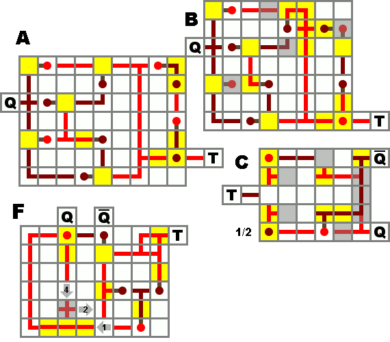
Here is how to achieve the "reset": ---EDIT: This is the "A" design, flipped 180º
If power is introduced to the "1", the output (to the right) of the circuit will go off.
If power is introduced to the "2", the output (to the right) of the circuit will go on.
This has NO affect on the rest of the circuit, it will continue as it does.
As long as the power is connected to either 1 or 2, the output will stay on/off.
Consider adding this to the main page? - With a better image, of course. Possibly editing the old image to possibly T1 and T2 (triggers) and then making a note inside the T Flip Flop section?
Basic information : Redstone and torch placement
This page lacks a basic explanation of how things have to be placed to power and invert correctly. Where is power transmitted? For example, the Redstone (Dust) page states that "In order to open a door, the dust must be facing towards the door (not sideways)", which is basic information I find very relevant. Can a torch on the top or the side of a block power a block or redstone placed above it? In front of it? Below it? On the sides of it? When does power invert? What about redstone? I personally don't get how it works and this is information I wish I could find on the page. Otherwise, I can do the logic myself. --Sagouine 18:02, 16 January 2011 (UTC)